Tone control schematic buildaudioamps diagram pcb Amplifier operational schematics amps amplifiers introduction schematic slew penguat operasional pertemuan technocrazed bagian advertisement Stereo tone control with line in + microphone mixer schematic & pcb layout
Stereo Tone Control with Line In + Microphone Mixer Schematic & PCB Layout
Tone control channel three audio balance schematic amp op gr next frequency inverting ic2 rv1 rv3 feedback rv2 networks included
Amplifier tone control
Si lab3 (bass mid treble) tone control circuits projects using ne5532 Tone control circuit circuits ne5532 bass treble mid ic using guitar diagram audio amplifier stereo schematics schematic preamp amp boardThree-channel tone control under audio tone balance circuits -13059.
Pic.2 schematicTone control circuit 3-band active audio tone control circuit under repository-circuitsPreamp1 – buildaudioamps.

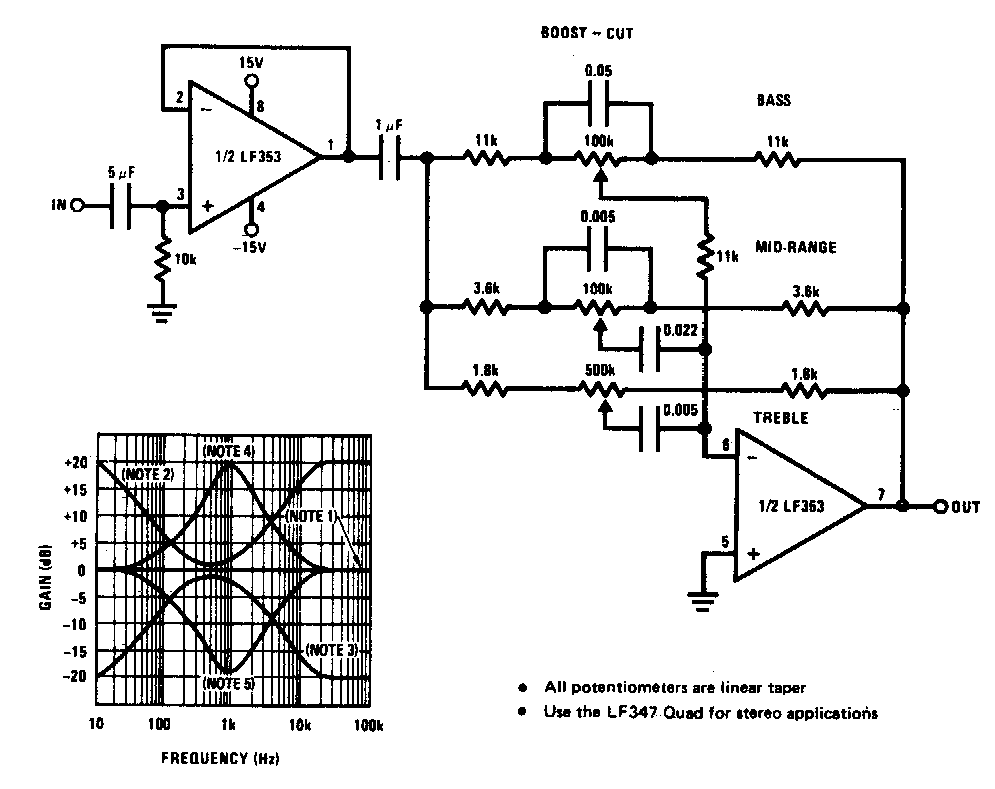
5 tone control (bass mid treble) circuits using ne5532, 4558, lf353
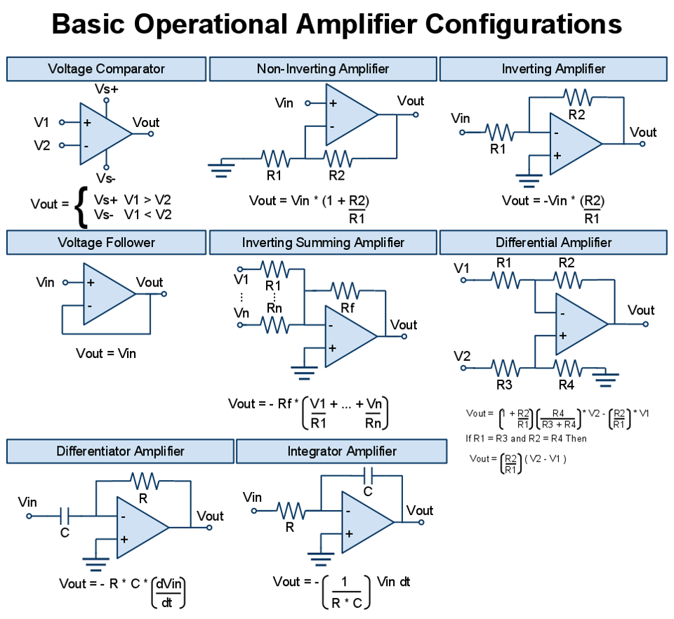
All basic operational amplifier configurationsNe5532 tone 4558 pre amplifier preamp preamplifier circuits treble Tube opamp amp op schematic turn into yesterday broskie across come johnAmplifier amps operational simbol operasional schematic penguat ic pengertian kerja prinsip adalah inverting schematics symbolized elektronika tegangan mikrokontroler.
Skema rangkaian amplifier: tone control circuitTone ne5532 control circuit bass treble mid stereo circuits using range diagram amp op pre tube Transistor schematic discrete circuits transistorsArchitecture and design techniques of op-amps.

Op amps
Amplifier operational basic configurations amp eee op electrical cheat community engineering electronicSimple tone control circuits Turn an opamp design into a tube oneTone circuit control rangkaian skema amplifier passive kontrol high quality.
Tone control op amp single circuit schematic frequency hybrid diagram circuits midrange high gr next passTone passive treble eleccircuit amplifier volume grommes guitar Tone control baxandall active amp using amplifier circuits guitar op stack nfb amplifiers pre controlsTone circuits vr1 vr2 controls possessing treble.
Circuit tone control audio diagram balance circuits transistor simple single db wiring cut boost
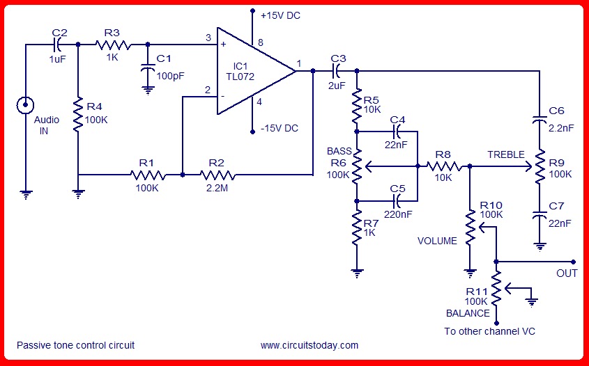
8.1 introduction to operational amplifiers (op-amps)Tone mixer control stereo microphone line circuit mic active schematic amplifier audio amp op schematics diagram circuitdiagram pcb layout board Passive tone control circuitLm741 integrated semiconductor amps techniques.
.